
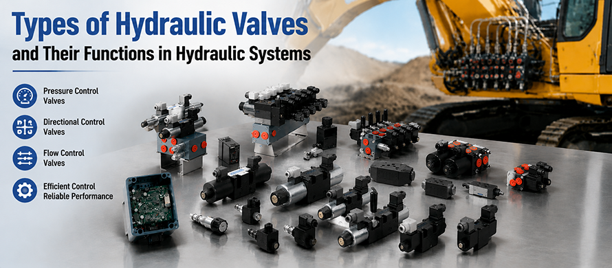
Hydraulic systems are widely used in industrial machinery, construction equipment, agricultural machines, and automated production systems because they can transmit large amounts of power with high efficiency and reliability. Within these systems, hydraulic valves play a critical role by controlling the movement, pressure, and flow of hydraulic fluid.
A hydraulic valve is a mechanical device that regulates the behavior of hydraulic oil inside a circuit. By controlling fluid direction, adjusting pressure levels, and managing flow rates, hydraulic valves allow hydraulic equipment to perform different operations accurately and safely.
The performance of a hydraulic system depends greatly on the proper selection and operation of valves. A suitable hydraulic valve can improve machine efficiency, reduce energy losses, protect system components, and provide precise control of hydraulic actuators such as cylinders and motors.
Hydraulic valves are available in many designs and configurations. They can be classified according to their functions, control methods, structural designs, and operating principles. The three main categories are pressure control valves, directional control valves, and flow control valves.
What Is a Hydraulic Valve?
A hydraulic valve is a control component used in hydraulic systems to start, stop, regulate, or redirect the flow of hydraulic fluid. It works by opening, closing, or partially restricting internal passages, allowing operators or automatic control systems to manage hydraulic energy.
Unlike simple mechanical switches, hydraulic valves can provide precise control over fluid power. They can maintain pressure within a safe range, control actuator speed, determine movement direction, and coordinate the operation sequence of multiple hydraulic components. In a typical hydraulic system:
- The hydraulic pump generates fluid pressure.
- Hydraulic valves control how the pressurized fluid is distributed.
- Hydraulic cylinders or motors convert hydraulic energy into mechanical movement.
Without hydraulic valves, a hydraulic system would not be able to achieve controlled movement or stable operation.
Classification of Hydraulic Valves
Hydraulic valves are generally divided into three major categories based on their primary function:
1. Hydraulic Pressure Control Valves
Pressure control valves regulate and maintain hydraulic pressure within a system. They prevent excessive pressure buildup and ensure that different components operate under suitable pressure conditions.
Common pressure control valves include:
- Relief valves
- Pressure reducing valves
- Sequence valves
- Counterbalance valves
- Unloading valves
These hydraulic valves are essential for protecting hydraulic equipment and improving system reliability.
2. Hydraulic Directional Control Valves
Directional control valves manage the path of hydraulic fluid through the circuit. They determine whether hydraulic actuators move forward, backward, stop, or remain in a neutral position.
Typical directional valves include:
- Two-way valves
- Three-way valves
- Four-way valves
- Multi-position spool valves
They are commonly used to control hydraulic cylinders and motors in industrial and mobile hydraulic applications.
3. Hydraulic Flow Control Valves
Flow control valves regulate the amount of hydraulic fluid passing through a system. Since actuator speed depends on fluid flow, these valves are mainly used for controlling movement speed.
Examples include:
- Needle valves
- Throttle valves
- Pressure compensated flow control valves
- Fixed flow control valves
Flow control valves help achieve smooth operation and accurate speed adjustment.
Hydraulic Pressure Control Valves
Pressure control valves are designed to maintain hydraulic system pressure at a desired level. Since hydraulic equipment often operates under high pressure, controlling pressure is necessary to avoid component damage and maintain safe working conditions.
These valves usually operate by using springs, pressure sensing mechanisms, or pilot control systems to adjust fluid flow according to pressure changes.
Pressure Relief Valve
A pressure relief valve is one of the most important safety components in a hydraulic system. Its primary purpose is to limit the maximum pressure within the circuit.
When system pressure rises above the preset value, the relief valve opens and allows excess hydraulic fluid to return to the reservoir. This prevents pressure overload and protects pumps, pipes, cylinders, and other hydraulic components.
Main Functions of Relief Valves:
- Prevent excessive system pressure
- Protect hydraulic components from damage
- Maintain safe operating conditions
- Control maximum pressure levels
Relief valves are commonly installed near hydraulic pumps because they provide immediate protection against pressure spikes.
Pressure Reducing Valve
A pressure reducing valve is used when different parts of a hydraulic system require different pressure levels.
While the main hydraulic circuit may operate at a high pressure, certain components may need lower pressure to function correctly. A pressure reducing valve lowers and maintains pressure in a specific branch of the system.
For example, a hydraulic machine may use high pressure for heavy lifting operations but require reduced pressure for control circuits or auxiliary functions.
Advantages of Pressure Reducing Valves:
- Provide stable lower pressure output
- Protect sensitive components
- Allow multiple pressure zones in one system
- Improve operational flexibility
These hydraulic valves are commonly found in complex hydraulic systems where different actuators require different working pressures.
Sequence Valve
A sequence valve controls the order in which hydraulic components operate. It ensures that one operation is completed before another begins.
The valve responds to pressure changes and allows fluid flow only after a predetermined pressure level has been reached.
For example, in a hydraulic clamping and drilling system, the clamp cylinder may need to secure the workpiece before the drilling cylinder starts moving. A sequence valve ensures that the correct order is maintained.
Applications of Sequence Valves:
- Automated production equipment
- Hydraulic presses
- Machine tools
- Material handling systems
Sequence valves are important for coordinating multiple hydraulic operations.
Counterbalance Valve
A counterbalance valve is designed to control the movement of hydraulic loads, especially when handling suspended or heavy components.
When a hydraulic cylinder is lifting or lowering a heavy load, the valve prevents uncontrolled movement caused by gravity. It creates resistance in the return line, allowing smoother and safer operation.
Main Benefits:
- Prevent sudden load dropping
- Improve load control
- Increase operator safety
- Provide stable cylinder movement
Counterbalance valves are commonly used in cranes, lifting platforms, excavators, and other heavy-duty hydraulic equipment.
Unloading Valve
An unloading valve is used to reduce unnecessary pressure when a hydraulic pump is operating without performing useful work.
When the system reaches a specific condition, the unloading valve redirects pump flow back to the tank at low pressure. This reduces energy consumption and minimizes heat generation.
Functions of Unloading Valves:
- Reduce power loss
- Improve system efficiency
- Lower operating temperature
- Extend component service life
They are often used in accumulator-based hydraulic systems and systems requiring intermittent operation.
Hydraulic Directional Control Valves
Directional control valves are one of the most commonly used types of hydraulic valves. Their main function is to control the direction of hydraulic fluid movement inside a hydraulic circuit. By changing the connection between inlet and outlet ports, these valves determine the direction in which hydraulic actuators move.
Hydraulic cylinders and motors rely on directional control valves to perform forward movement, reverse movement, stopping, and holding operations. Without directional control valves, hydraulic systems would not be able to control the motion sequence of machines.
These valves are widely applied in:
- Industrial hydraulic machinery
- Injection molding machines
- Construction equipment
- Agricultural machinery
- Automated manufacturing systems
Working Principle of Directional Control Valves
A directional control valve operates by changing internal flow passages to control hydraulic oil movement. The valve contains internal components such as spools, poppets, or rotary elements that move between different positions.
When the valve changes position, hydraulic fluid is directed through different ports, allowing the actuator to move in a specific direction. For example:
- When pressure oil enters one side of a hydraulic cylinder, the piston extends.
- When fluid is directed to the opposite side, the piston retracts.
- When the valve blocks or redirects flow, the actuator stops or remains stationary.
The movement of the internal valve element determines how hydraulic energy is transferred throughout the system.
Directional Valve Ports and Positions
Hydraulic directional valves are usually identified by the number of ports and operating positions.
The common naming method uses two numbers:
The first number represents the number of ports.
The second number represents the number of operating positions.
For example:
- A 2/2 directional valve has two ports and two positions.
- A 3/2 directional valve has three ports and two positions.
- A 4/3 directional valve has four ports and three positions.
The combination of ports and positions determines the possible flow paths and operating functions of the valve.
Two-Way Directional Control Valve
A two-way valve contains two ports:
- Inlet port
- Outlet port
It controls whether hydraulic fluid can pass through the circuit or not.
The valve usually operates in two positions:
- Open position: Hydraulic fluid flows freely through the valve.
- Closed position: The flow path is blocked, stopping fluid movement.
Two-way valves are commonly used for simple on/off hydraulic control applications.
Three-Way Directional Control Valve
A three-way valve contains three ports and is often used for single-acting hydraulic cylinders. The three ports usually include:
- Pressure port
- Cylinder port
- Tank port
Depending on the valve position, hydraulic fluid can be supplied to the actuator or returned to the reservoir.
These valves are frequently used in applications where one hydraulic direction and one return path are required.
Four-Way Directional Control Valve
Four-way valves are widely used in hydraulic systems because they can control double-acting cylinders and reversible hydraulic motors.
A typical four-way valve includes:
- Pressure port (P)
- Tank port (T)
- Work port A
- Work port B
The valve changes the connection between these ports to control actuator movement.
For example:
- Forward Movement: Pressure oil flows from the pump to port A, while fluid from port B returns to the tank. The cylinder extends.
- Reverse Movement:Pressure oil flows to port B, while oil from port A returns to the tank. The cylinder retracts.
Spool Type Directional Control Valves
Many hydraulic directional valves use a spool design. A spool valve contains a cylindrical sliding element that moves inside the valve body.
The spool contains lands and grooves that open or close different flow passages depending on its position.
When the spool shifts:
- Some ports become connected.
- Other ports become blocked.
- Hydraulic fluid changes direction.
Spool valves are popular because they provide reliable operation, compact structure, and flexible control options.
They can be designed with different center configurations depending on the requirements of the hydraulic system.
Directional Valve Control Methods
Hydraulic directional valves can be operated using different control methods. The choice depends on the application, automation level, and operating environment.
The main control methods include:
Manual Operated Directional Valves
Manual valves are controlled directly by an operator through handles, levers, or mechanical controls. Advantages:
- Simple structure
- Low cost
- Easy maintenance
They are commonly used in small hydraulic systems and equipment requiring direct human operation.
Pilot Operated Directional Valves
Pilot operated valves use hydraulic pressure to control the movement of the main valve element.
A smaller pilot valve generates the control force required to shift the main spool. Advantages include:
- Ability to control high-pressure systems
- Lower operating force
- Suitable for large hydraulic equipment
These valves are commonly used in heavy industrial machinery.
Solenoid Operated Directional Valves
Solenoid valves use electrical signals to control hydraulic flow.
An electromagnetic coil moves the valve element when electrical power is applied. Advantages:
- Fast response
- Easy automation
- Remote operation capability
Solenoid directional valves are widely used in automated hydraulic systems.
Solenoid Controlled Pilot Operated Valves
This type combines electrical control with hydraulic pilot operation.
A small solenoid valve controls pilot pressure, which then shifts a larger main valve. This design provides:
- Electrical control convenience
- High flow capacity
- Reliable operation under high pressure
They are commonly used in large hydraulic systems requiring accurate electronic control.
Directional Valve Flow Path Classification
Directional valves can also be classified according to the number of flow paths they provide.
- Two-Way Valves: Two-way valves control a simple fluid passage by allowing or blocking flow between two ports. They are mainly used for basic switching operations.
- Four-Way Valves: Four-way valves provide more complex control by directing hydraulic fluid between multiple ports. They are mainly used for controlling double-acting cylinders and reversible hydraulic motors.
Directional Valve Position Classification
The number of positions determines how many operating states the valve can provide.
Two-Position Valves
Two-position valves have two operating states. Typical functions include:
- Open and closed
- Forward and reverse
- Start and stop
They are commonly used for simple hydraulic control.
Three-Position Valves
Three-position valves provide an additional neutral position between two operating directions. A typical three-position valve can provide:
- Forward movement
- Neutral holding
- Reverse movement
The center position can be designed differently depending on system requirements.
Spool Center Configurations
The center design of a directional valve determines the hydraulic behavior when the valve is in the neutral position. Different center configurations are available for different applications.
Open Center Valve
In an open center design, the pressure port is connected to the tank port when the valve is neutral. Characteristics:
- Pump flow returns freely to the tank
- Lower standby pressure
- Suitable for open-center hydraulic systems
Closed Center Valve
In a closed center design, all ports are blocked when the valve is in the neutral position. Characteristics:
- Maintains system pressure
- Suitable for pressure-compensated pumps
- Allows multiple valves to operate independently
Partially Closed Center Valve
A partially closed center design combines features of open and closed center systems.
Some ports remain connected while others are blocked, providing specific flow control characteristics.
Semi-Open Center Valve
A semi-open center valve provides limited flow through certain passages when in neutral.
It is designed for systems requiring controlled pressure release while maintaining partial hydraulic connection.
Tandem Center Valve
A tandem center valve connects the pressure port to the tank while blocking the actuator ports. This allows pump unloading while holding the actuator position. Advantages:
- Reduces energy consumption
- Prevents unnecessary pressure buildup
- Provides stable actuator holding
Spring Arrangements in Directional Control Valves
The position of a directional valve spool can be controlled by springs. Different spring designs determine how the spool returns after operation.
Spring Offset Valve
A spring offset valve uses a spring to return the spool to a default position after the control force is removed. It is commonly used where automatic return operation is required.
Spring Centered Valve
A spring centered valve uses springs on both sides of the spool to keep it in the central neutral position. When the control force is removed, the spool automatically returns to the center. Applications include:
- Mobile hydraulic equipment
- Industrial control systems
- Machinery requiring neutral holding
No Spring Valve
A valve without spring return remains in the selected position until another control signal moves it. These valves are suitable for applications where continuous positioning is required.
Hydraulic Flow Control Valves
Flow control valves are another major category of hydraulic valves. Their primary purpose is to regulate the amount of hydraulic fluid flowing through a system, which directly affects the operating speed of hydraulic actuators.
In hydraulic systems, the speed of a cylinder or motor is mainly determined by the volume of fluid supplied to it. By adjusting the flow rate, flow control valves allow operators and control systems to achieve accurate movement speeds and smoother machine operation.
These valves are widely used in applications where precise speed control is required, including:
- Industrial automation equipment
- Hydraulic presses
- Machine tools
- Construction machinery
- Material handling systems
Working Principle of Hydraulic Flow Control Valves
A hydraulic flow control valve works by changing the size of the fluid passage inside the valve. By increasing or decreasing the opening area, the valve controls how much hydraulic oil can pass through within a specific period. When the flow rate increases:
- Hydraulic actuators move faster.
- Machine operating speed increases.
When the flow rate decreases:
- Actuator movement becomes slower.
- More precise control can be achieved.
Proper flow regulation helps prevent sudden movement, vibration, and unstable operation of hydraulic equipment.
Relationship Between Flow Rate and Actuator Speed
In a hydraulic system, actuator speed is directly related to the amount of fluid supplied to the actuator. For hydraulic cylinders:
- Higher flow volume results in faster piston movement.
- Lower flow volume results in slower piston movement.
For hydraulic motors:
- Increased flow produces higher rotational speed.
- Reduced flow decreases motor speed.
Therefore, selecting the correct flow control valve is important for achieving the desired machine performance.
Types of Hydraulic Flow Control Valves
Hydraulic flow control valves are available in different designs depending on the required level of control, pressure conditions, and application requirements. The common types include:
- Movable flow control valves
- Pressure compensated flow control valves
- Fixed flow control valves
- Throttling flow control valves
Movable Flow Control Valve
A movable flow control valve allows the operator or control system to adjust the opening size and change the fluid flow rate. The valve position can be manually adjusted or controlled automatically depending on the design. Advantages:
- Flexible flow adjustment
- Suitable for variable operating conditions
- Easy control of actuator speed
These valves are often used where equipment needs different operating speeds during different working stages.
Pressure Compensated Flow Control Valve
A pressure compensated flow control valve maintains a relatively constant flow rate even when system pressure changes.
In normal hydraulic systems, pressure variations can affect fluid flow. When the load changes, the flow rate may increase or decrease, causing inconsistent actuator speed.
A pressure compensated valve automatically adjusts the internal opening to compensate for pressure fluctuations. Benefits include:
- Stable actuator speed
- Improved precision
- Better performance under changing loads
These valves are commonly used in advanced hydraulic equipment requiring accurate speed control.
Fixed Flow Control Valve
A fixed flow control valve provides a predetermined flow rate that cannot be adjusted during operation.
The internal passage size is fixed, allowing the valve to deliver a consistent amount of fluid. Advantages:
- Simple construction
- Reliable operation
- Low maintenance requirements
Fixed flow valves are suitable for systems where constant flow conditions are acceptable.
Throttling Flow Control Valve
A throttling valve controls flow by restricting the passage of hydraulic fluid. The restriction creates resistance, reducing the amount of oil that can pass through the valve. Throttling valves are commonly used for:
- Speed adjustment
- Motion control
- Hydraulic circuit balancing
However, because throttling creates pressure loss, these valves may generate heat and reduce system efficiency in some applications.
Hydraulic Flow Control Valve Design Types
Flow control valves can also be classified according to their internal design structure. Common designs include:
- Ball valves
- Butterfly valves
- Diaphragm valves
- Needle valves
- Plug valves
Each design provides different flow characteristics and is selected according to application requirements.
Ball Flow Control Valve
Ball valves use a rotating ball with a hole through its center to control fluid flow.
When the hole aligns with the flow path, fluid can pass through. When the ball rotates, the passage becomes restricted or closed. Advantages:
- Quick operation
- Compact structure
- Good sealing performance
Ball valves are commonly used in applications requiring simple on/off control.
Butterfly Flow Control Valve
Butterfly valves use a rotating disc mounted inside the valve body.
When the disc rotates, it changes the opening area and controls the amount of fluid passing through. Advantages:
- Lightweight design
- Compact size
- Suitable for large flow applications
They are often used in systems where space and weight are important considerations.
Diaphragm Flow Control Valve
A diaphragm valve uses a flexible membrane to regulate fluid movement.
The diaphragm moves upward or downward to control the opening and adjust flow. Advantages:
- Good sealing ability
- Reduced contamination risk
- Suitable for special fluid conditions
These valves are useful in applications requiring clean and reliable fluid control.
Needle Flow Control Valve
Needle valves use a tapered needle-shaped element to precisely adjust flow.
Because the needle provides fine control over the opening size, these valves are suitable for applications requiring accurate flow adjustment. Advantages:
- High precision control
- Smooth flow adjustment
- Suitable for low-flow applications
They are commonly used in precision hydraulic circuits.
Plug Flow Control Valve
Plug valves use a rotating cylindrical or tapered plug to regulate fluid flow.
By changing the position of the plug, the valve controls the size of the flow passage. Advantages:
- Simple structure
- Reliable sealing
- Easy maintenance
They are used in various industrial fluid control applications.
Hydraulic Flow Measurement Methods
Hydraulic flow can be measured in several different ways depending on the application requirements.
The three common measurement methods are:
- Mass flow rate
- Weight flow rate
- Volumetric flow rate
Mass Flow Rate
Mass flow rate measures the amount of fluid mass passing through a specific point over a certain period.
This measurement method is useful when fluid density changes need to be considered. Applications include:
- Industrial process control
- Precision fluid systems
- Advanced hydraulic monitoring
Weight Flow Rate
Weight flow rate measures the weight of fluid moving through a system over time.
This method considers the effect of gravity and fluid weight.
It is commonly used in engineering calculations involving fluid force and system performance.
Volumetric Flow Rate
Volumetric flow rate measures the volume of fluid passing through a point within a specific time period.
This is one of the most common methods used in hydraulic systems.
It is typically expressed in units such as:
- Liters per minute (L/min)
- Cubic meters per hour (m³/h)
Volumetric flow measurement is widely used for selecting and evaluating hydraulic components.
Conventional Flow Control Valve Applications
Flow control valves are used in many hydraulic systems where controlled movement and speed regulation are required. Typical applications include:
- Industrial Machinery: Manufacturing equipment uses flow control valves to achieve accurate movement and stable production processes.
- Construction Equipment: Excavators, loaders, and cranes rely on flow control valves to control hydraulic actuator speed and improve operator control.
- Agricultural Machinery: Farm equipment uses hydraulic flow control for lifting, steering, and attachment control.
- Automated Systems: Robotic and automated hydraulic equipment require precise flow regulation for repeatable movement.
How to Select the Right Hydraulic Valve
Choosing the correct hydraulic valve requires consideration of several factors.
- Operating Pressure: The valve must be able to withstand the maximum pressure of the hydraulic system. Selecting an unsuitable pressure rating may lead to leakage, failure, or reduced service life.
- Flow Requirements: The valve capacity should match the required hydraulic flow rate. An undersized valve can cause excessive pressure loss and reduce system efficiency.
Control Method: The appropriate control method depends on the application:
- Manual control for simple systems
- Solenoid control for automation
- Pilot control for high-pressure applications
- Proportional control for precision systems
Operating Environment: Environmental conditions such as temperature, contamination, vibration, and operating frequency should also be considered when selecting hydraulic valves.
Final Thoughts on Hydraulic Valve Types and Applications
Hydraulic valves are fundamental components that allow hydraulic systems to operate efficiently, safely, and accurately. By controlling fluid direction, pressure, and flow, hydraulic valves determine how hydraulic energy is distributed and used throughout a machine.
Pressure control valves protect systems by maintaining safe pressure levels. Directional control valves manage the movement direction of hydraulic actuators. Flow control valves regulate operating speed and ensure smooth machine performance.
Different hydraulic applications require different valve designs and control methods. Understanding the characteristics, operating principles, and applications of various hydraulic valve types helps engineers select the right components and build more reliable hydraulic systems.
As hydraulic technology continues to develop, advanced valve designs such as proportional and electronically controlled valves will continue to improve system efficiency, automation capability, and precision across industrial applications.