
Are you looking for a high-quality Hydraulic Solenoid Valve? If so, you’ve come to the right place. Bstind is one of China’s leading manufacturers of hydraulic solenoid valves, dedicated to providing reliable and efficient fluid control solutions to customers around the world.
With so many models and complex specifications on the market, many purchasers and engineers often find themselves confused: What exactly are the differences between various valve structures? How do they actually work?
Don’t worry. This article will walk you through the working principles of common hydraulic solenoid valves in the most straightforward way, giving you a clearer understanding of product selection and application — so you can make the best and most cost-effective choice.
To understand the working principle of a hydraulic solenoid valve, it is important to first recognize that its primary function is to control the direction of hydraulic fluid flow. To gain a deeper understanding of how a hydraulic solenoid valve operates, we need to understand the basic working principle of the solenoid valve, as well as the different types and models available. Although hydraulic solenoid valves come in various designs, their fundamental working principles remain the same.
Hydraulic Solenoid Valves Working Principle
A hydraulic solenoid valve is an automation component used to control fluid flow and belongs to the category of actuators.
The hydraulic solenoid valve controls the direction of hydraulic flow. In factories, hydraulic cylinders are commonly used to control mechanical equipment, and hydraulic solenoid valves are used to control the operation of these cylinders. So, what is the working principle of a hydraulic solenoid valve?
Hydraulic solenoid valve working principle:
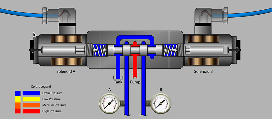
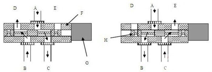
A hydraulic solenoid valve has a closed chamber with multiple openings located at different positions, and each opening is connected to a different oil pipe. Inside the chamber, there is a piston (spool) located in the middle, with two solenoid coils installed on both sides. When an electric current is applied to one of the solenoid coils, the electromagnetic force moves the valve body toward that side. By controlling the movement of the valve body, the valve can open or close different oil passages while keeping the inlet port continuously open. The hydraulic oil then flows into the corresponding oil pipes and uses oil pressure to push the cylinder piston. The piston drives the piston rod, and the piston rod moves the mechanical device. In this way, the mechanical movement can be controlled by switching the solenoid current on and off.
Hydraulic Solenoid Valve Operating Principle Diagram:
(1)WE-type solenoid directional valve figures 1, 2, 3, and 4 illustrate the structural designs of WE-type solenoid directional valves in different sizes.
Although WE-type solenoid directional valves are available in various models and specifications, their basic operating principles are the same. The solenoid controls the position of the slide valve spool, allowing the hydraulic oil flow path to be changed according to different spool positions. When the solenoid coil is not energized, the spring automatically returns the spool to the neutral or initial position (except for pulse-type valves). In addition, the spool can be manually moved by pressing the fault inspection button.
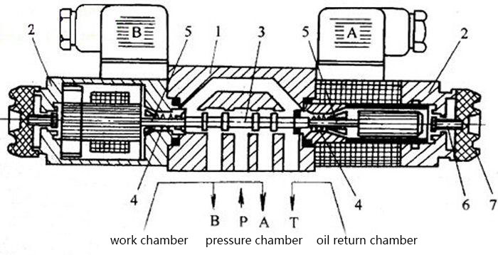
Figure 1 WE5 type solenoid directional valve structure schematic diagram
What is the working principle of the hydraulic solenoid valve, hydraulic solenoid valve principle dissection – page 2
1-valve body; 2-solenoid (left for AC solenoid, right for DC magnet); 3-slide valve; 4-reset spring; 5-pusher; 6-fault check button; 7 -Rubber protective cover
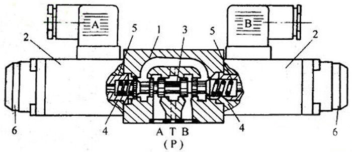
Figure 2 Structure schematic diagram of WE6 type solenoid directional valve
1-valve body; 2-solenoid; 3-slide valve; 4-reset spring; 5-pusher; 6-fault check button
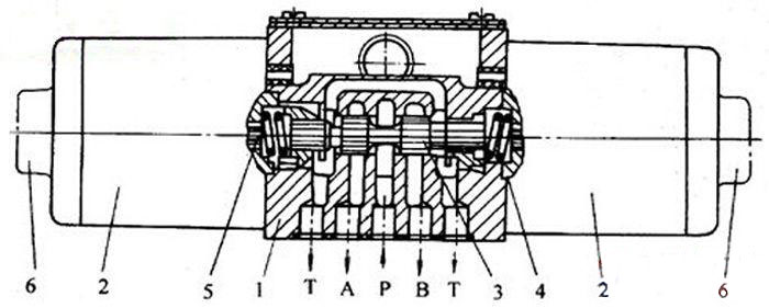
Figure 3 4WE10E10/A type wet solenoid directional valve structure principle diagram
1-valve body; 2-wet indication solenoid; 3-slide valve; 4-reset spring; 5-push rod; 6-fault check button
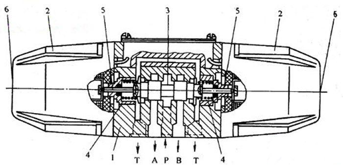
Figure 4 Structure schematic diagram of 4WE10E10/L…type dry AC solenoid directional valve
1-valve body; 2-dry solenoid; 3-slide valve; 4-reset spring; 5-pusher; 6-fault check button
Hydraulic solenoid valve model meaning:
Different manufacturers may use different coding systems to identify hydraulic solenoid valve models. Taking the model 34BYM-L20H-T as an example, each letter and number represents a specific feature of the valve. The code 34 indicates a 3-position, 4-way valve; B represents the AC type; Y refers to hydraulic activation; M indicates the slide valve function; L specifies the threaded connection type; 20 represents the nominal diameter; the first H indicates the nominal pressure, while H also refers to the high-pressure rating of 31.5 MPa; and T represents the medium spring code.
Characteristics of hydraulic solenoid valves:
- The hydraulic solenoid valve features external leakage prevention, while internal leakage is easy to control, ensuring safe and reliable operation.
- The hydraulic solenoid valve system has a simple structure, making it easy to maintain and offering a relatively low cost.
- The hydraulic solenoid valve provides fast response, requires low power consumption, and has a compact and lightweight design.
Classification of hydraulic solenoid valves:
A hydraulic solenoid valve is a key component used in hydraulic transmission systems to control the pressure, flow rate, and direction of hydraulic fluid. Within a hydraulic solenoid valve system, the pressure control valve is responsible for adjusting fluid pressure, while the flow control valve regulates the flow rate. The directional control valve controls the opening and closing of the hydraulic circuit and determines the direction of fluid flow.
Other classifications of control valves:
1. Directional control valves can be classified into check valves and directional valves according to their applications.
Check valve: A check valve allows fluid to flow only in one direction. When the fluid flows in the opposite direction, the valve closes and blocks the passage.
Directional valve: A directional valve changes the connection relationship between different pipelines. According to the number of working positions of the spool inside the valve body, it can be divided into two-position, three-position, and other types. Based on the number of controlled ports, it can be classified into two-way, three-way, four-way, five-way, and other configurations. According to the spool operating method, it can be divided into manual, mechanical, electrical, hydraulic, and other types.
2. Pressure control valves can be divided into relief valves, pressure reducing valves, and sequence valves.
- Relief valve: A relief valve maintains the hydraulic system pressure at a preset value. When used for overload protection, it is called a safety valve. If the system pressure increases to the specified limit due to a malfunction, the valve port opens to release excess pressure, ensuring system safety and preventing possible damage.
Pressure reducing valve: A pressure reducing valve controls the pressure of a branch circuit to maintain a stable pressure lower than the main circuit pressure. According to different pressure control functions, pressure reducing valves can be divided into three main types: fixed-value pressure reducing valves, fixed-differential pressure reducing valves, and fixed-ratio pressure reducing valves.
Sequence valve: A sequence valve controls the operating sequence of actuators, allowing one actuator to operate before another actuator starts.
Flow control valves regulate flow by adjusting the throttle opening area between the valve spool and valve body, thereby changing the local resistance and controlling the movement speed of the actuator. According to their functions, flow control valves can be divided into five types.
- Speed control valve: A speed control valve maintains a constant pressure difference between the inlet and outlet of the throttle valve, even when the load pressure changes.
- Flow divider valve: Regardless of load variations, a flow divider valve can distribute flow from the same oil source equally between two actuators. It can also provide proportional flow distribution through a proportional flow divider valve.
- Flow divider and collector valve: This type of valve combines the functions of both a flow divider valve and a collector valve.
- Collector valve: A collector valve combines incoming flows according to a specific proportion. Its function is opposite to that of a flow divider valve.
- Throttle valve: After adjusting the throttle opening area, the throttle valve can maintain a relatively stable actuator movement speed. Even under significant changes in load pressure, it helps ensure smooth and uniform actuator movement.
Principle of hydraulic solenoid valve
In a pump pipeline system, when the pump suddenly stops, the check valve at the pump outlet closes rapidly. This causes the circulating flow in the outlet pipeline to decrease suddenly, generating a reverse flow impact pressure. The sudden change in flow velocity creates a shock pressure wave that propagates at a very high speed. As a result, the pressure at the valve outlet section may increase to several times the rated pressure. This phenomenon is known as water hammer in the pipeline system, which may cause damage to the valve or pipeline and lead to potential accidents.
To prevent this type of problem, various valves with delayed closing characteristics are currently used, such as two-stage controlled closing butterfly valves, hydraulic control valves with main and auxiliary valve plates, and slow-closing check valves. These valves delay the closing process, allowing part of the water flow to return through the pump and rotor components to release pressure and reduce the water hammer effect. However, because the pressure relief process takes a relatively long time, the continuous reverse flow can impact the pump impeller for an extended period. This may cause the pump rotor components and the connected motor rotor components to rotate in the reverse direction, resulting in long-term damage.
To overcome these issues, an automatic pressure relief valve can be installed on the bypass pipeline. During pressure relief, the valve allows the return flow to bypass the pump inlet, preventing the pressure relief backflow from passing through the pump rotor components. After the pressure relief process is completed, the valve automatically closes. This design completely eliminates the impact of reverse pressure relief flow on pump reverse rotation and effectively prevents water hammer.
Hydraulic Solenoid Valves Structural design
The valve is composed of a valve body, hydraulic chamber, and hydraulic pipes A and B. The valve body adopts a four-port tubular structure and is equipped with a hydraulic actuator rod, upper valve plate, and lower valve plate. Both ends of the hydraulic actuator rod are threaded. The lower section of the valve body is fastened to the bottom cover by connecting bolts. The upper and lower sections of the valve body are provided with inlet and outlet ports, which are connected to the external pipeline system. A sealing seat is installed at the center of the valve body near the upper inlet and outlet ports. The upper valve plate is welded to the hydraulic actuator rod, while the lower valve plate is fixed to the rod through a threaded connection and nut. The hydraulic chamber is mounted on the upper part of the valve body through a flange connection.
The hydraulic chamber is composed of a hydraulic chamber seat, hydraulic chamber cover, hydraulic chamber body, and piston. These components are assembled together and fixed to the valve body using screws and nuts. The hydraulic chamber seat is covered by the chamber seat cover, and the piston is installed inside the hydraulic chamber body. The hydraulic actuator rod passes through the chamber seat cover and is secured with a nut. The threaded end of the actuator rod is connected to the piston. The piston separates the hydraulic chamber into two independent sections: the upper chamber and the lower chamber.
An O-ring seal is installed on the piston to form a pressure-tight seal between the piston and the inner wall of the hydraulic chamber, ensuring complete separation of the upper and lower chambers. A through-hole is designed in the hydraulic chamber cover, allowing hydraulic pipe A to connect with the upper chamber. Similarly, the hydraulic chamber seat is equipped with a through-hole, through which hydraulic pipe B is connected to the lower chamber.
O-ring seals are installed on the upper valve plate, lower valve plate, and hydraulic chamber seat cover. Gaskets are placed between the contact surfaces of the hydraulic chamber cover and hydraulic chamber body, between the hydraulic chamber body and hydraulic chamber seat, between the hydraulic chamber seat and valve body, and between the valve body and bottom cover to ensure sealing performance. In addition, hydraulic pipe A is equipped with a strainer, control valve, and micro check valve, while hydraulic pipe B is fitted with a strainer and control valve. The hydraulic chamber cover contains a through-hole connected to the hydraulic pipe, and a micro check valve is installed on the hydraulic pipe. A bleeder screw plug is installed at the top of the hydraulic chamber cover to release air from the upper chamber.
The hydraulic chamber is assembled from the hydraulic chamber seat, hydraulic chamber cover, hydraulic chamber body, and upper diaphragm plate. The diaphragm, diaphragm gland, and upper diaphragm plate are installed inside the hydraulic chamber body. The diaphragm is positioned above the diaphragm plate, while the diaphragm gland is located below it. The hydraulic transmission rod passes through the hydraulic chamber seat and is fixed with a nut. The threaded end of the hydraulic transmission rod is connected with the diaphragm gland, integrating the diaphragm and diaphragm plate into one assembly. Finally, the hydraulic chamber cover, diaphragm, and hydraulic chamber body are fastened together using screws and nuts. The diaphragm divides the hydraulic chamber into upper and lower chambers, completely isolating the two sections.
Hydraulic Solenoid Valves Principle of Operation and Function
The above-mentioned bypass hydraulic pressure relief valve structure is designed for use in fluid transportation pipeline systems. It is installed on the bypass pressure relief line at the outlet side of the pump outlet check valve. Through this installation method, the valve can achieve the following operating functions and effects:
When the pump starts running, the pressure in the hydraulic pipe connected to the lower chamber of the hydraulic cavity is higher than that in the hydraulic pipe connected to the upper chamber. Due to this pressure difference, the piston moves upward. The hydraulic actuator rod then drives the lower valve plate to move upward accordingly. At this stage, fluid enters the valve through the lower inlet and outlet ports and flows out through the upper inlet and outlet ports.
As the piston moves upward, the hydraulic drive rod pushes the lower valve plate upward until it contacts the sealing seat inside the valve body. The “O” sealing ring is compressed to form a sealing effect. At this moment, fluid flow through the upper and lower inlet and outlet ports is blocked, and the pump and pipeline system operate normally. The hydraulic pipe connected to the valve cover helps increase the flow velocity of the fluid inside the hydraulic cavity, thereby accelerating the operation process.
When a sudden power interruption occurs, the check valve closes automatically. At this time, the pressure in the upper chamber of the hydraulic cavity becomes higher than that in the lower chamber. Driven by this pressure difference, the piston moves downward and causes the lower valve plate to move downward through the hydraulic drive rod. As the lower valve plate moves away from the sealing seat, the “O” sealing ring loses its sealing function, allowing fluid to enter from the upper inlet and outlet ports, pass through the valve, and discharge through the lower inlet and outlet ports.
At the same time, the hydraulic drive rod drives the upper valve plate downward together with the lower valve plate until the upper valve plate contacts the valve body and sealing seat. The “O” sealing ring is compressed again to restore sealing, preventing further fluid from entering through the upper inlet and outlet ports and eliminating the hydraulic impact effect. During this process, both the upper and lower valve plates move downward simultaneously. The period from the initial loss of sealing performance of the “O” sealing ring until it restores sealing is defined as the pressure relief time.
Gaskets are used to prevent leakage of fluid from the hydraulic cavity and to ensure that fluid does not escape from the valve body. The “O” seal installed on the hydraulic chamber seat cover separates the fluid inside the hydraulic cavity from the valve body. A control valve is installed on the hydraulic pipe to adjust the pressure relief time. By regulating the control valve opening, the inflow and outflow rates of fluid in the upper and lower chambers of the hydraulic cavity can be controlled, thereby adjusting the pressure relief duration.
A filter is installed in the hydraulic pipe to remove impurities from the fluid and maintain cleanliness inside the hydraulic chamber. A micro check valve is also installed on the hydraulic pipe to throttle the fluid entering the upper chamber of the hydraulic cavity. This design ensures flexible valve operation and allows adjustable closing time. The closing time can be adjusted from a minimum of 15 seconds to a maximum of 348 seconds. For complex pipeline systems, this valve can effectively reduce water hammer effects and provides an effective solution to the problems of slow-closing two-stage check valves, such as reverse flow impact and pump reverse rotation.
Hydraulic Solenoid Valves Applications
Bstind have developed and manufactured three models of pressure relief valves with nominal diameters of 80 mm, 150 mm, and 300 mm, all rated at a nominal pressure of 1.6 MPa. These valves are suitable for water pipelines, metallurgical cooling circulation systems, and petrochemical cooling water circulation pipelines. After approximately oBne year of practical operation, the results show that the valves operate reliably with flexible movement. The closing time can be adjusted according to the requirements of different complex pipeline systems, effectively reducing the influence of water hammer. This design successfully solves the problem of long closing times found in two-stage shut-off check valves and eliminates the reverse water hammer caused by return flow. The test results demonstrate that the structural design and performance parameters of the valve are reasonable, and the selected design parameters are accurate.
The bypass hydraulic control pressure relief valve is installed on the bypass pipe of the main pipeline, specifically at the outlet side of the check valve. By using the pressure of the pipeline fluid, the valve can automatically control and drive the operation of the check valve. This design overcomes the limitations of traditional two-stage closing valves and provides an effective solution to the problems commonly found in conventional valve systems.
In traditional valve systems, leakage during the process of eliminating water hammer pressure may cause the pump rotor components to reverse, resulting in potential damage. The bypass hydraulic control pressure relief valve effectively avoids this problem. In addition, the valve is equipped with an adjustable closing time function, allowing it to adapt to different complex pipeline conditions and effectively suppress water hammer pressure. Therefore, it represents a new type of pressure relief valve with broad application prospects.
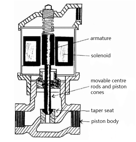
A solenoid valve is an automatic control component used for controlling fluid flow and is classified as an actuator. Its applications are not limited to hydraulic systems but also include pneumatic systems. The solenoid valve controls the direction of hydraulic fluid flow. In industrial factories, mechanical equipment is often operated by hydraulic systems, and solenoid valves are commonly used to control these hydraulic functions.
The operating principle of a solenoid valve is based on a closed chamber containing multiple ports at different positions, with each port connected to a separate oil pipe. A valve spool is located in the center of the chamber, and electromagnetic coils are installed on both sides. When one of the electromagnetic coils is energized, the generated magnetic force moves the valve body toward that side. This movement changes the opening and closing status of different oil passages.
Meanwhile, the inlet port remains open, allowing hydraulic oil to flow into the corresponding outlet passages. The hydraulic pressure then pushes the piston, causing the piston rod to move and drive the connected mechanical equipment. In this way, the operation of mechanical devices can be controlled by switching the current supplied to the electromagnet on or off.
Contact Bstind professional team for the latest production technology!